Specialized Techniques Used in Assembling Flexible Printed Ci
Unlike rigid PCBs that are made from materials like FR4, fiberglass and epoxy resins, flex circuits are typically made of polyimide, an organic material with excellent elasticity. This allows them to withstand the repeated tight bending and dynamic flexing found in modern products such as laptops, tablet computers, fitness trackers and cellular phones.
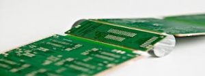
Rigid flexible printed circuit board and assemblies are hybrid constructions that combine both the benefits of a rigid board with those of a flexible one. They are typically made of multiple layers of a flexible polyimide base layer plus a rigid conductive material such as copper.
These are commonly used in high-density interconnection applications such as those seen in mobile devices. The conductors are often plated on both sides of the board and connect to a component or other element through a copper-plated through hole. Rigid flex circuits are also widely used in computer peripherals including moving print heads, read/write heads and the arms on disk drives.
Are There Any Specialized Techniques Used in Assembling Flexible Printed Ci?
When creating a flex circuit, the copper foil is normally etched with conductive patterning and then bonded to the dielectric substrate using an adhesive. Copper is the conductor of choice for most flex circuit applications because it provides an excellent balance of cost, physical performance and durability, and electrical properties. The exposed areas of the traces are normally coated with gold or solder to prevent corrosion and improve the conductive properties of the copper.
The etching and bonding process can be accomplished in various ways depending on the needs of the design. While the traditional method of printing a copper pattern on the surface is still used by some manufacturers, photo imaging or laser imaging are now more popular. These methods are also quicker and more precise.
When designing a flex circuit, it is important to consider the maximum amount of bending that will occur during its intended use. The amount of deflection can be controlled by choosing the right layer count, the etching process and the material thickness. In addition, a designer should always choose the highest quality copper foil available to minimize the risk of the flex circuit failing due to fatigue failure. This is normally achieved by selecting a higher grade of rolled annealed copper that can be stretched longer before fatigue cracking begins.
Another consideration is the way that flex circuits are terminated to their components. It is important to choose a slit or slot with a tangential radius greater than 180deg in order to reduce the chance of the flex circuit substrate being torn at those corners. If this is not possible, a relief hole should be placed at these locations.
During the assembling process, skilled operators must ensure that all of the connections are properly aligned and connected. The resulting assemble is then tested for defects, such as short circuits or opens, and visual inspection is carried out to look for contaminants and scratches on the bare circuit boards. This helps to ensure that the final product performs as required.